Quick Answer
A two-wire cable assembly should be specified by more than a photo or a connector shape. For an accurate quote and repeatable production build, an OEM should provide the connector part numbers or clear identification details, polarity and pinout, wire gauge and insulation, finished length and tolerance, current and voltage conditions, operating environment, and required test records. A reference image is useful for discussion, but the approved drawing and bill of materials control the final assembly.
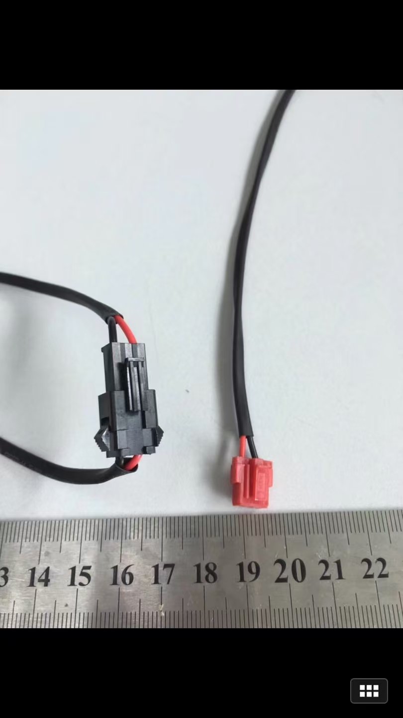
The image above shows a compact two-wire inline cable assembly with red and black conductors, protective black sleeving, a black locking inline connector, and a small red two-position connector. The ruler provides a useful scale reference. It does not, by itself, establish the connector series, terminal specification, wire size, electrical rating, or test limits.
What Is a Two-Wire Cable Assembly?
A two-wire cable assembly is a finished interconnect made from two insulated conductors, terminated with connectors, terminals, or other end features for a specific application. It commonly carries DC power, a simple sensor circuit, a low-current control connection, or another two-conductor circuit. Its performance depends on the complete system: conductor size, insulation, terminals, connector keying, strain relief, routing, polarity, and test requirements.
For procurement teams, the key point is simple: two assemblies can look alike while using different mating interfaces, polarity assignments, conductor sizes, or environmental ratings. Those differences can prevent installation or create a functional or safety risk.
Why a Photo Is Helpful but Not Production Data
A clear photo can speed up early communication. It may reveal:
- Approximate connector size, color, latch style, and number of positions
- Visible red/black conductor color convention
- Overall cable routing and branch-free construction
- Sleeving, heat-shrink, labels, or strain-relief features
- Approximate finished length when a scale reference is included
However, a photo cannot reliably identify hidden features such as terminal plating, terminal crimp range, exact connector keying, conductor cross-section, insulation temperature rating, or cavity-level pin assignment. Treat the photo as a visual reference, then convert it into controlled specifications before production.
The RFQ Checklist for a Two-Wire Cable Assembly
1. Identify Both Connector Interfaces
Provide manufacturer and part numbers for each connector housing, terminal, seal, and mating part whenever available. If the part number is unknown, send close-up images of every side, the connector dimensions, cavity count, latch/keying details, and a photo of the mating connector.
Do not identify a connector only as “two pin” or by its color. Many connector families have a similar appearance but do not mate, have different current limits, or use different terminals.
2. Define Polarity and Pinout
State which conductor connects to each cavity at both ends. For a two-wire power lead, document the positive and negative path explicitly; do not rely on red and black colors alone. Include a simple pin-to-pin table, schematic, or drawing revision.
| End A cavity | End B cavity | Circuit | Conductor color |
| 1 | 1 | Positive / circuit A | Red |
| 2 | 2 | Negative / return | Black |
The table above is only a format example. The approved electrical design must define the actual assignment.
3. Specify Wire Construction and Finished Length
For each conductor, provide:
- Conductor size: AWG or mm²
- Stranding requirement, if relevant
- Insulation material, color, and temperature rating
- Finished cable length and how it is measured
- Length tolerance, including any critical connector-to-connector dimension
- Required sleeving, tubing, tape, braid, labels, or overmolding
Define whether length is measured between connector faces, from wire exit to wire exit, or from a stated datum. This prevents a small but important difference from becoming a fit issue at installation.
4. Describe Electrical and Environmental Conditions
Give the application conditions that influence material and termination selection:
- Maximum operating voltage and current
- Continuous duty, switching duty, or signal function
- Temperature range
- Flexing, vibration, pull, bend radius, or installation constraints
- Moisture, dust, washdown, oil, chemicals, UV, or outdoor exposure
- Shielding or electromagnetic compatibility needs, where applicable
State requirements as project-specific engineering inputs. Do not assume that a connector or sleeve seen in a sample automatically meets an environmental or compliance requirement.
5. Set Quality and Test Requirements
At a minimum, many cable assemblies require a continuity, pin-mapping, and short-circuit check. Depending on the application, the responsible engineering team may also specify pull-force, dimensional, insulation-resistance, dielectric-withstand, sealing, or functional tests.
Include the acceptance criteria, sample quantity, drawing revision, and required inspection record. If a workmanship standard, customer specification, or market requirement applies, provide its exact revision and clarify which portions apply to the assembly.
From Reference Image to Controlled Build Data
The fastest reliable process is to use the photo as the first input—not the only input:
1. Identify the visible connector interfaces and cable features.
2. Confirm mating parts and polarity with a drawing or pin-to-pin netlist.
3. Lock conductor, insulation, length, and protection details.
4. Define test coverage and documentation.
5. Approve a first article or sample against the controlled revision.
6. Release the production revision and manage changes formally.
This workflow gives sourcing teams a clearer comparison between quotes and gives production teams measurable acceptance criteria.
Procurement Questions to Ask Before Selecting a Supplier
Can the Supplier Quote from a Sample Photo?
Yes, a supplier can often use a photo for an initial discussion or budgetary estimate. A production quote should be based on confirmed connectors, pinout, wire specification, dimensions, quantity, and test expectations.
What Information Has the Largest Effect on Quote Accuracy?
Connector and terminal part numbers, wire specification, harness length, volume, test requirements, and delivery expectations usually have the greatest impact. Missing any of these can lead to assumptions that must be resolved later.
How Should an OEM Handle an Unknown Connector?
Provide measurements, clear photos, cavity count, latch and keying features, mating-side images, and a physical sample if sharing is permitted. The final connector selection should be confirmed against the approved product design before production.
How WireAssyTech Can Help
WireAssyTech can begin a custom cable assembly discussion from a reference image, sample, or existing documentation. For a production-ready quotation, provide the supporting technical data above and identify any critical fit, electrical, test, traceability, or delivery requirements. Material availability, validation scope, compliance, and lead-time commitments should be confirmed for the specific project before release.
Frequently Asked Questions
Can a red and black wire pair define polarity by itself?
No. Red and black are useful visual conventions, but the approved drawing or pinout must define the actual circuit assignment and connector cavity orientation.
Can I use a ruler in the photo to define cable length?
A ruler provides helpful context, but it is not a substitute for a controlled finished-length dimension and tolerance on a drawing or RFQ.
What should I send if I have no drawing?
Send the physical sample if permitted, high-resolution photos of both connectors and the mating interfaces, dimensions, available equipment information, and any known electrical details. The final design must still be approved by the responsible OEM engineer.
What tests are common for a two-wire cable assembly?
Continuity, correct pin mapping, and short-circuit checks are common. Additional testing must be selected and limited by the application’s engineering requirements.
Suggested Internal and External References
Before publishing hyperlinks, verify the live WireAssyTech service URLs and use natural anchors such as custom cable assembly, wire harness manufacturing, and request a quote. For external technical context, cite authoritative sources appropriate to the project, such as UL Solutions information for applicable wire and cable requirements, connector manufacturer datasheets, and the applicable IPC/WHMA-A-620 revision. Do not imply certification or standard compliance unless it is confirmed for the specific product and facility.